
Understanding motherboard adapter connections
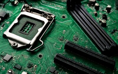
What is a motherboard adapter connector and why it matters
A pulse of possibility travels through every build when a connector finds its mate. A recent figure shows upgrade flexibility sits at the top of priorities for 68% of PC builders, a vivid reminder that compatibility is more than a convenience. Understanding these connectors reveals an artful architecture built for longevity.
What is a motherboard adapter connector? It is the bridge between the board and the wider world of expansion, power, and peripherals. When chosen with care, these connectors safeguard signal integrity, ease installation, and smooth future upgrades. The terms may be technical, but the result is elegant stability that endures thanks to motherboard adapter connectors.
Here are essentials for readers across South Africa—clean, practical insights that breathe elegance into choice.
- Data interfaces and pinouts
- Power delivery compatibility
- Physical form factor and alignment
For builders chasing reliability, the choice of motherboard adapter connectors matters.
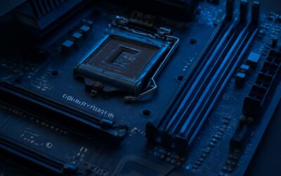
Key signal and power roles of adapter connectors
Connections aren’t mere links; they’re the hinge on which your build pivots. In South Africa, upgrade flexibility tops the list for 68% of PC builders, and “Compatibility is survival,” as one expert puts it. Understanding motherboard adapter connectors reveals how signal and power weave a stable backbone.
These connectors handle the key signal and power roles that keep data flowing and components humming. They guard impedance, ensure clean data paths, and stabilize rails so peripherals behave as expected. Key roles include:
- Signal integrity and impedance control
- Robust power delivery for rails
- Precise physical alignment for reliable mating
When these elements align, a quiet, almost supernatural stability settles over the system.
From a bustling Cape Town workshop to a Johannesburg bench, I’ve watched how the tiny choices around motherboard adapter connectors determine longevity. They are the silent guardians of your build’s coherence, keeping data and power in harmony long after the first boot.
Overview of common form factors and pin layouts
Across South Africa, upgrade flexibility drives decisions for many builders. About 68% say compatibility is essential, and that mindset hinges on one thing: motherboard adapter connectors. These tiny interfaces quietly determine whether data flows smoothly and rails stay stable under load.
In practice, expect a handful of common form factors and pin layouts. The 24-pin ATX main power, 8-pin EPS CPU power, and PCIe 6- or 8-pin connectors anchor most builds, with USB headers and front-panel pins following predictable spacing for tidy installs.
These layouts aren’t cosmetic; they stop impedance drift and mis-mating dead in its tracks, keeping systems singing from boot to burn-in.
How adapters influence upgrade paths and system compatibility
Across South Africa, upgrade flexibility guides every build. 68% say compatibility is essential, a beacon that points directly at motherboard adapter connectors. These tiny interfaces quietly choreograph whether a modern GPU slides in, whether a legacy drive still sings, and whether power rails remain steady when the system strains.
- Bridge legacy and contemporary standards to unlock future upgrade paths
- Preserve power integrity and signaling across adapters
- Maintain form-factor and header pinout harmony for tidy installations
- Mitigate impedance drift and mis-mating, safeguarding boot sequences
Understanding these connections becomes a map for South African builders, revealing how adapters influence upgrade paths and system compatibility. When the right connectors align with your motherboard, data flows like a smooth chorus and stability follows through the burn-in. The phrase ‘motherboard adapter connectors’ isn’t just hardware talk—it’s the weather signal of a future-ready PC.
Types of adapter connectors used in motherboards
CPU and PCIe adapter connectors
In the quiet math of a PC build, a single connector can tilt the odds. Two main families govern the game: CPU adapters and PCIe adapters. CPU adapters feed the heart of the system with stable voltages via EPS12V and ATX12V variants, while PCIe adapters supply the extra amperage for graphics cards and other PCIe devices. The right pairing matters for stability, upgrade headroom, and long-term compatibility in South Africa’s diverse hardware market.
- CPU power adapters: 4-pin ATX12V and 8-pin EPS12V configurations
- PCIe power adapters: 6-pin and 8-pin (6+2) connectors for GPUs
- Newer PCIe 5.0/12VHPWR options: 16-pin power delivery for high-end cards
Together, these motherboard adapter connectors shape upgrade possibilities and overall system reliability, ensuring that the setup meets the demands of modern builds.
RAM and DIMM-related adapters
RAM choices hinge on the fit between memory modules and DIMM-related adapters. Desktop boards welcome larger DIMMs, while laptops rely on compact SODIMMs—each path demands a compatible motherboard adapter connectors. DDR generations from DDR3 to DDR5 shape the memory landscape, with ECC and non-ECC options influencing reliability and cost. The right pairing preserves dual‑channel potential and upgrade headroom in South Africa’s diverse hardware market.
- Desktop DIMMs (DDR3/DDR4/DDR5) and typical motherboard sockets
- SODIMM modules for laptops and mini-ITX boards
- ECC vs non‑ECC, UDIMM vs RDIMM variants
Memory typing isn’t merely about speed. The notch positions, loading balance, and BIOS support influence stability more than raw MHz. When you evaluate motherboard adapter connectors for RAM, you’re aligning generations, density, and channel configuration—an unseen but decisive factor in future upgrades.
I/O shield and backplate adapters
In the quiet world behind your case, tiny connectors do the heavy lifting. A striking 63% of technicians report build delays caused by misaligned I/O shields, often traced to the wrong type of motherboard adapter connectors.
Types of adapter connectors used in motherboard I/O shield and backplate adapters fall into practical families:
- Pin-header style paths that route USB, audio, and LAN through the shield
- Crimped blade contacts for compact backplates with tidy cables
- Magnetic or snap-on interfaces for quick alignment in tight cases
- Soldered contact rings on premium shields for solid ground continuity
The right balance of these options preserves shielding, grounding, and signal integrity—hallmarks of dependable motherboard adapter connectors.
In South Africa’s diverse hardware market, the best matches keep systems future‑proof and compatible with a wide range of enclosures.
Storage interface adapters and connectors (SATA, NVMe, M.2)
In the storage stack, the right adapter connector can make or break performance. SATA, NVMe, and M.2 interfaces each demand a precise fit to preserve throughput and endurance. The umbrella category, motherboard adapter connectors, must accommodate signal integrity and correct lane allocation so drives sing rather than stutter.
What you’ll encounter in practice is a compact set of families designed to suit different form factors and budgets:
- M.2 edge connectors: Key M for NVMe PCIe paths; Key B/M variants handle SATA or PCIe, with 2242/2260/2280 lengths.
- SATA data and power pins: the classic 7-pin data plus 15-pin power for 2.5″ drives, or slim adapters for LFF/2.5″ bays.
- U.2/PCIe connectors (SFF-8639) and compatible cables: NVMe drives that demand higher throughput and hot-swap capability.
In South Africa’s diverse configuration landscape, these connector families guide future‑proofing and enclosure compatibility without sacrificing grounding and shielding.
Legacy vs. modern connector families
South African builders know that the rhythm of a PC starts at the motherboard, not in the GPU. “The path of the signal is the lifeblood of performance,” a veteran tech reminded me, and it’s the truth behind motherboard adapter connectors. Legacy and modern families duel for bandwidth, grounding, and form-factor fit—the tiny gates that decide throughput and endurance.
- Legacy families rely on IDE/PATA and PCI card-edge connections that echo older chassis.
- Modern families embrace M.2 edge connectors, U.2, and PCIe paths that prize speed and compactness.
- Hybrid approaches balance power, shielding, and enclosure constraints to keep compatibility across SA configurations.
Standards and compatibility considerations
Industry standards and naming conventions
Standards are the quiet rails that keep builds on track. The right alignment means fewer headaches and smoother upgrades for motherboard adapter connectors. In South Africa, that reliability is priceless.
Industry bodies like PCI-SIG, SATA-IO, and USB-IF publish revisions that ripple through every motherboard and adapter. Naming conventions—PCIe generations and lane counts, NVMe versus SATA, backplate identifiers—guide compatibility at a glance and keep projects from stalling.
- Read the PCIe generation and lane count (e.g., PCIe 4.0 x16)
- Match SATA/NVMe interfaces and M.2 keying
- Confirm backplate and form-factor alignment with the chassis
Voltage, signaling, and timing compatibility
“The handshake that keeps a build alive is the quiet force that decides boots or stalls!” In South Africa, voltage, signaling, and timing compatibility govern the success of motherboard adapter connectors, where even a tiny mismatch can ripple through power rails and PCIe lanes, stalling upgrades and frictions.
- Voltage rails align with device expectations to prevent damage or instability
- Signal integrity across PCIe, SATA, and NVMe paths
- Timing margins accommodate clock domains and retries
Industry bodies like PCI-SIG, SATA-IO, and USB-IF publish revisions that define compatible behavior. By favoring standards and validating backplate and form-factor alignment, engineers keep projects from stalling and maintain upgrade paths with confidence.
Physical form factor and mounting compatibility
Standards shape the heartbeat of every build, and form factor dictates the rhythm of space, airflow, and cabling. A tiny misalignment in screw holes, slot pitch, or shield recess can stall a project faster than a power spike—like a whisper from a silent guardian, reminding us that compatibility is a living guarantee.
Physical form factor and mounting compatibility determine whether a chassis and motherboard share the same DNA. Industry blueprints for backplates, I/O shields, and screw locations keep the assembly anchored, even as components evolve.
- ATX, microATX, and mini-ITX family patterns with standard screw spacings
- Extended and server form factors where backplates differ
- Specialty chassis variants needing precise shield cutouts
With these standards in play, motherboard adapter connectors align cleanly and reliably.
BIOS/UEFI compatibility and whitelist concerns
Standards govern how far a board can bend the limits of a build, and compatibility is the quiet gatekeeper of success. BIOS/UEFI expectations can make or break a swap of motherboard adapter connectors, especially as vendors lock boot behavior behind firmware whitelists. I’ve seen projects stall at this gate, and a sharp review of form-factor intent and firmware notes keeps a build moving forward as firmware evolves.
- BIOS/UEFI compatibility, path to support the adapter and chipset pairing
- Firmware update routes, rollback, and recovery options
- Vendor whitelist policies, certification requirements, and cross-platform validation considerations
In South Africa’s repair and warranty channels, firmware compatibility often wins or loses the day. I’ve learned to check that the chosen adapter path aligns with your motherboard’s whitelist posture, and to confirm available updates before committing to a bridge that could stall a build mid-spark.
Cross-vendor compatibility tips and caveats
Firmware gates stall more builds than you’d expect—especially when you’re navigating motherboard adapter connectors. Standards guardrails determine how far a build can push the limits, while compatibility acts as the quiet gatekeeper. For motherboard adapter connectors, the interplay of form factor, signal integrity, and mounting tolerance guides what bridges truly function across brands, including South Africa.
In practice, cross-vendor compatibility requires careful verification of these factors:
- Pin layouts, voltage rails, and timing must align across brands for these adapters to function predictably.
- Firmware and BIOS behavior, especially whitelist controls, can silently block unsupported adapters after updates—plan for this.
- Certification and cross-platform validation from vendors reduce warranty headaches and post-purchase surprises.
In a market where firmware evolves, a cautious review of standards and notes keeps builds alive rather than haunting them with incompatibility ghosts.
Installation, configuration, and optimization tips
Choosing the right adapter for your motherboard model
Across South Africa, upgrades that click into place shorten cycle times by as much as 20%, simply because the right adapter fits your model. I’ve witnessed cases where the correct selection for motherboard adapter connectors transforms a jittery rig into a steady, humming workhorse!
Installation, configuration, and optimization start with a light touch and mindful checks. Ground yourself, seat connectors without force, and verify form factor and pin layouts. BIOS/UEFI readiness matters as much as the hardware itself. Here are guiding considerations:
- Compatibility with form factor and pin layout
- Signal integrity and power delivery compatibility
- BIOS/UEFI readiness and vendor whitelists
Choosing the right adapter for your motherboard model is the hinge of a lasting build. Study the manuals, verify vendor support, and weigh future upgrade paths. When you align with the motherboard adapter connectors, the system will sing.
Step-by-step installation best practices
A clean, deliberate install saves more time than a spare tool in a South African workshop. When it comes to motherboard adapter connectors, lift the hood gently, ground yourself, and line up pins with care before any seating or power goes on.
- Power down, unplug, and discharge static; keep the workspace clean and dry.
- Align form factor, pin layout, and connector guides with care—no forcing.
- Gently seat all connectors, then verify with a light wiggle and a look-over.
- Power up, enter BIOS/UEFI, and confirm recognition before finalizing changes.
Final checks: a quick power-on self-test confirms stability, BIOS/UEFI recognizes the hardware, and basic post checks progress without drama.
Avoiding common installation mistakes and damage prevention
Across South Africa’s growing PC-building scene, a tidy install translates into real time saved. They say: “Patience is the highest form of speed,” and in this field the truth feels almost lyrical. When the moment arrives to pair cables and adapters, a calm approach shields components and future upgrades alike.
With motherboard adapter connectors, alignment, respect for form factor, and avoidance of force matter more than drama. The idea is to honor the design language of the motherboard: line up guides, never rush, and accept the quiet satisfaction of a well seated system. After initial seating, a gentle look-over and a check in the BIOS/UEFI can confirm the path forward, before any power is applied.
Post-installation testing and performance checks
Across South Africa’s growing PC-building scene, tidy post-install checks save real time. For motherboard adapter connectors, alignment and form-factor respect translate into reliability and smoother upgrades—I’ve seen it pay off!
During configuration, BIOS/UEFI should recognize every adapter and map signals to the intended lanes. Optimization comes from balanced power, clean airflow, and avoiding tension around motherboard adapter connectors.
Post-install testing and performance checks are observational, not exhaustive. Note stability, thermals, and storage throughput.
- BIOS/UEFI shows adapters without errors
- Temperatures stay within expected ranges
- Storage throughput matches expectations
- System reboots and throttling remain normal
In the quiet spaces between firmware updates, patience remains the highest form of speed. Respect for motherboard adapter connectors today pays dividends in stability tomorrow.
Troubleshooting common adapter connector issues
Symptoms that indicate a faulty adapter connector
Startup nights are hard; as one veteran technician puts it, “Power is a subtle culprit.” A flicker of LEDs, a fan that stutters, and the system stalls—yet the culprit may be invisible: motherboard adapter connectors. These slender interfaces quietly govern power and data routes, and when they falter, the whole build bears the mark of instability.
Symptoms creep in with the quiet menace of a ghost touch. Common telltales include these indicators:
- System boots inconsistently or stalls during POST
- Peripherals drop in and out, or USB devices fail to enumerate
- BIOS reports missing devices or voltage warnings
Visible clues—warped pins, scorching smells, or heat around sockets—signal a fault that outlives optimism; trust those signals and consider the broader context of contact integrity in the realm of motherboard adapter connectors.
Systematic diagnostic workflow
Power gremlins rarely arrive with fanfare; as a seasoned technician says, ‘Power is a subtle culprit.’ That observation frames the drama of motherboard adapter connectors: when they misbehave, the system stalls, LEDs flicker, and peripherals falter. A systematic diagnostic workflow anchors decisions to the integrity of these slender interfaces.
- Visual inspection for bent pins, scorching smells, or heat around sockets.
- Reseat power cables and boards to confirm proper seating.
- Swap in known-good adapters to isolate the fault.
- Check BIOS/UEFI device enumeration and boot logs.
- Observe voltage rails with safe, minimal-load monitoring.
With this workflow, symptoms become traceable rather than mysterious, guiding precise repairs and reducing downtime.
Repair, replacement, and upgrade pathways
Troubleshooting common adapter connector issues begins with a calm inventory of the tiny interfaces that quietly drive a system. When power stalls or peripherals misbehave, the culprit often hides at the edge of the motherboard. A disciplined routine—visual inspection, careful reseating, and safe-voltage checks under light load—turns chaos into traceable fault, letting you distinguish a tired connector from a failing component. These motherboard adapter connectors deserve respect for the way they tether performance to reliability.
- Repair: reseat, clean, and inspect for bent pins; reestablish reliable contact with proper seating.
- Replacement: source exact-match adapters, verify pinouts, and test with known-good mates.
- Upgrade: select higher-bandwidth or more robust interfaces where the board supports them to extend lifespan.
With this approach, every fault path becomes a clean decision—repair, replace, or upgrade—minimizing downtime and preserving system integrity.
Safety considerations and warranty implications
Reliability rides on the edge of the motherboard—the tiniest connectors often tell the tale before fans spin. The edge is where stability either hides or surfaces, a veteran technician once said, and I felt that truth in my bones. When gaps flicker and peripherals misbehave, the motherboard adapter connectors reveal the story—quietly, insistently!
Safety considerations for handling them go beyond a casual checklist. Static discipline, proper grounding, and respectful contact protect both hardware and warranty. Damage from improper handling is often treated as user-caused, potentially voiding cover.
Warranty implications: read the policy—many brands reserve remedies for issues arising from normal use rather than pin-bending or forced connections. Document anything unusual and seek official guidance from your SA vendor if concerns arise, preserving options when the system needs to endure another day.

0 Comments