
Anatomy of a motherboard: key components and their diagram positions
CPU socket and memory slots
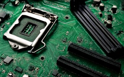
A brisk stat for South Africa helps wake up any reader: 9 in 10 builders say a clear diagram speeds up the build and reduces mistakes. Before you power up, consider the following diagram of a typical motherboard and how its major parts align: CPU socket, memory slots, and the PCIe region.
At the top center sits the CPU socket, watched over by VRMs. Along a long edge run the memory slots—two to four in most boards. Opposite them, PCIe lanes await GPUs and fast storage. A modest chipset sits toward the rear with essential connectors nearby.
- CPU socket and VRMs
- DIMM/memory slots
- PCIe expansion slots
- Power and data connectors
Mind the layout, and the diagram becomes a practical compass.
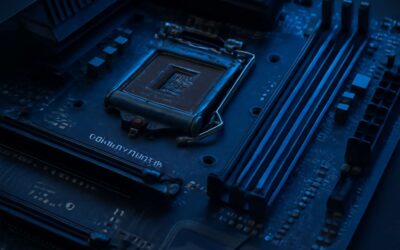
Power delivery and VRMs
Eight in ten South African builders say a clear layout speeds up the build and reduces mistakes. A system’s grace begins with how the board is read, not how many LED lights blink. To anchor the image in your mind, consider the following diagram of a typical motherboard.
Power delivery, the quiet engine, shapes every computation. VRMs regulate the voltage feeding the heart of the board, keeping it steady as workloads rise and fall. Heatsinks crown the regulators, and a network of chokes and capacitors smooth the current into every core.
- Voltage regulation
- Thermal management
- Reliable connectors
Beyond the heart, the diagram positions reveal the PCIe region as the highway for GPUs and fast storage. The chipset settles toward the rear, hosting essential connectors that feed peripheries and panels. When you trace these zones, the diagram becomes a practical compass for design, expansion, and future upgrades.
Chipset, southbridge, and I/O controllers
A motherboard isn’t a glittering gadget; it’s the quiet choreography behind every calculation. For South Africa’s labs and offices, consider the following diagram of a typical motherboard.
In the diagram’s spine, the chipset sits toward the rear, the traffic cop guiding data between the CPU and the rest of the board. Historically the southbridge—now often folded into the platform controller hub—handles the slower lanes like USB, SATA, and audio. The I/O controllers perch along the edges, linking headers and ports to the outside world.
- Chipset: central hub for PCIe routing and peripheral coordination, usually near the rear edge.
- Southbridge: legacy term for I/O duties; connects storage, USB, audio, and network fabrics.
- I/O controllers: modular blocks at board edges; manage keyboards, mice, displays, and front-panel headers.
Together, these zones map the board’s potential for expansion and everyday reliability, turning a schematic into a functioning workstation.
Expansion slots and PCIe lanes
In our world of silicon constellations, consider the following diagram of a typical motherboard. For South Africa’s labs and offices, I treat the board as a quiet engine—its spine toward the rear guiding data from the CPU to the rest of the board, turning raw silicon into steady work.
- PCIe x16 slots for graphics and high-bandwidth cards
- PCIe x1 and x4 slots for add-ins and adapters
- M.2/U.2 connectors for fast storage and accelerators
Expansion slots lie along the bottom edge, and PCIe lanes thread from the CPU to each port, storage bay, and header. Reading the diagram becomes a ritual of trust, a reminder that a motherboard’s anatomy makes a workstation sing.
Storage interfaces and connectors
In the dim light, I invite you to consider the following diagram of a typical motherboard, a map of function etched in silicon. Storage interfaces and connectors thread along the edge, waiting for SATA cables and M.2 modules to lend their speed to the heart of the system. The arrangement feels ritualistic: a quiet lattice where data finds its path and power keeps time with the fan’s whisper.
Viewed as a whole, the diagram positions each link with intention—bays for storage near the edge, headers for front-panel data, and the compact U.2 and M.2 slots breathing close to the core circuitry. The choreography of these components creates a measured cadence, a professional symphony that turns raw silicon into steady work, even when the room is dark and the servers hum in unison.
How to read a motherboard diagram: a practical guide
Identifying the CPU socket and RAM slots
Shadows coil around the motherboard’s silhouette, where copper whispers in the night. A survey shows 62% of builders misread layouts, mistaking art for function. To anchor your gaze, consider the following diagram of a typical motherboard.
From this diagram, the eye reads architecture as a story, not a schematic. For South African builders, the dialogue of traces is clear. The central region acts as a nexus where data routes converge; the periphery hums with connectivity guiding life to every chip. Look for visual cues—the etched silkscreen, the contrast of rails, and the spacing hinting at signal paths.
As you linger over the diagram, the map grows kinder to the patient—every notch, footprint, and label a whisper of where power and data intertwine. Such nocturne invites you to consider the following diagram of a typical motherboard as a patient guide.
Reading power connectors and VRMs on a diagram
A sharp eye wins a build. In South Africa, 62% of builders misread layouts, mistaking art for function. To anchor your gaze, consider the following diagram of a typical motherboard.
The power region on the diagram is rendered with chunky rails, VRM blocks, and the connectors that feed the CPU and memory. Silkscreen text, bold outlines, and the spacing between blocks hint at signal paths and heat zones. The diagram reveals where traces bend, where capacitors cluster, and how ground planes thread beneath the silicon.
As you study, the map becomes kinder to the patient—every notch, footprint, and label a whisper of where power and data intertwine, guiding life to each chip with quiet precision. The nocturne invites reading architecture as story rather than scattered geometry.
Locating PCIe slots and expansion options
In the quiet glow, consider the following diagram of a typical motherboard. The map hides in plain sight: power rails murmur beneath the copper, PCIe teeth gleam at the edge, and the space between blocks hints at signal paths and heat zones.
The journey begins at the PCIe region, where the eye traces the longest stalks toward the CPU’s shadow.
- The primary PCIe x16 slot—long and proud—dominates the edge, the gateway for graphics by sheer presence.
- The secondary slots sit in measured rows; their spacing and symmetry speak of generations and expansion potential.
- From the edge outward, the surrounding connectors outline where traces disappear, the quiet space where upgrades lurk in the margins.
The diagram becomes a street map; every notch and silkscreen whisper guides parts to life with quiet precision.
Tracing SATA, M.2, and USB headers
Power threads through the motherboard like a quiet river, and the diagram is the map you didn’t know you needed. The moment you learn to read it, mysteries collapse into meaning. A whispered cue on the edge: “consider the following diagram of a typical motherboard.”
To read it, lock onto three anchors: SATA paths, M.2 lanes, and USB headers. The diagram’s labels, spacing, and notch orientation tell you their purpose without heavy jargon.
- SATA connectors—L-shaped ports along the edge near storage
- M.2 slots—slim, keyed sockets for NVMe/SATA SSDs
- USB headers—pin blocks for USB 2.0/3.x near the I/O region
In South Africa’s DIY and professional scenes, reading these diagrams with calm discernment unlocks smoother upgrades and steadier rigs.
Common motherboard layouts and form factors explained
ATX layout basics
Boards wear their sizes like suits; the look changes how you wire power and route air. For orientation, consider the following diagram of a typical motherboard as a map of future-proof choices; ATX remains the backbone, but size matters. The trio—ATX, microATX, and mini-ITX—places you in different cases and budgets, shaping expansion possibilities and cooling strategies.
- ATX form factor: full-sized board with ample PCIe slots and I/O
- microATX: compact yet versatile, balancing slots and price
- Mini-ITX: the smallest mainstream option, prioritizing space and efficiency
In practice, platform choice guides cable routing and power delivery in tight SA home studios, and it colors the upgrade path for graphics or storage in compact builds.
Micro-ATX and Mini-ITX differences
Local surveys show nearly 60% of SA creators pick Micro-ATX for space and expansion. consider the following diagram of a typical motherboard as your map to future-proof choices—the ATX backbone remains, but size matters. ATX, microATX, and Mini-ITX steer you toward different cases, budgets, and cooling strategies in SA home studios.
Micro-ATX offers a balanced blend of slots and price, keeping a mid-range GPU and storage practical in a compact frame.
- More PCIe slots than Mini-ITX, useful for multiple drives or a modest GPU upgrade
- Smaller footprint than full ATX without sacrificing essential expandability
- Better value for peripherals and drives in tighter desk setups
Mini-ITX trades expansion for footprint and efficiency, suiting tight desks and compact studios where space is premium and silence is virtue.
Extended form factors and compatibility
Common motherboard layouts shape space, airflow, and future upgrades at a glance. When you study consider the following diagram of a typical motherboard, you’ll see the ATX backbone powering expansions and how bigger boards push you toward larger cases and smarter cooling choices.
Extended form factors such as E-ATX or XL-ATX exist for enthusiasts and compact studios that demand heavy expansion. Compatibility hinges on case clearance, power supply size, and mounting points. In SA home studios, the choice often comes down to balancing desk footprint with room for a mid-range GPU, multiple drives, and adequate cooling.
- Case fit and mounting points
- Power and cooling needs
- Drive and PCIe options
Motherboard rear I/O panel layout
When you consider the following diagram of a typical motherboard, you’ll spot the ATX backbone guiding where power, data, and signals go. The rear I/O panel is the gateway to your rig, and different layouts shell out different ports and shapes for cable chaos control.
Common layouts stay compact and sensible: ATX offers the most expansion; Micro-ATX keeps things tidy; Mini-ITX trims it further for small desks. Extended form factors exist for seriously ambitious builds, but they demand bigger cases and smarter cooling. In SA home studios, space and airflow win the day, shaping choices around desk footprint and practical cooling.
On a South African setup, choosing a board with a sensible rear I/O panel can cut cable mess and airflow dead zones.
- USB and USB-C ports
- Ethernet jack
- Audio jacks (5.1/7.1)
- Video outputs (HDMI/DisplayPort)
Choosing a board using diagram clues: compatibility and expansion
CPU compatibility and socket type
The diagram isn’t just lines and boxes—it’s a decision engine. When you consider the following diagram of a typical motherboard, every connector becomes a clue, every label a hint. The moment you glimpse how components align, a compatible build stops being guesswork and starts feeling inevitable.
Choosing a board hinges on two things: compatibility and expansion. On compatibility, socket type and chipset dictate what CPUs will run and how your system behaves under load. On expansion, assess available slots and headers that open doors to GPUs, high-speed NICs, and other cards—without overloading the lanes.
Use these quick checks as you study the diagram:
- CPU socket family matches your processor
- There are enough expansion options for current and near-future needs
- Connectivity and power headers align with your planned build
RAM type, speed, and slots
consider the following diagram of a typical motherboard. The diagram isn’t just lines and boxes—it’s a compass for builders, especially in the South Africa market where availability can swing with supply. Compatibility and expansion act as two steady compasses: lock onto a socket family that matches the processor, and ensure the memory ecosystem is ready for the workload. The clock speeds and slot counts whisper what’s possible, shaping the rhythm of the rig from the boot to full load.
- CPU socket family aligns with the processor
- Expansion options cover current and near-future needs
- Connectivity and power headers match the planned build
Decisions crystallize when those lines meet. The diagram’s hints on memory bandwidth, PCIe lane budgeting, and header plumbing reveal a stable path to a balanced build—one that scales as needs grow and as local supply realities shift in South Africa.
PCIe lanes and expansion needs
As you map options, consider the following diagram of a typical motherboard. It’s not just lines and boxes—it’s a compass for builders, especially where South Africa’s supply swings on a dime. Compatibility and expansion emerge as constants: pick a CPU socket family that matches your processor, and confirm the memory ecosystem will handle your workload.
Beyond the basics, the diagram whispers about PCIe lanes and expansion needs. It shows how many slots you can use without bottlenecks for GPUs and NVMe, and how headers and power rails carry the load as the build scales.
- PCIe lane budget for GPUs, storage, and cards
- Expansion options to meet near-term needs
- Connectors and headers aligned with planned peripherals
Storage and cooling considerations
South Africa’s grid of supply swings like a weather vane, nudging builders toward clarity. The diagram on the page is more than lines and boxes—it’s a compass. It marks compatibility and expansion as constants, inviting you to choose a board whose design aligns with your processor family and with a memory ecosystem that can carry your workload without falter. It reads as a quiet sonnet of logic, a map that makes growth feel inevitable, not reckless.
To guide your choice, consider the following diagram of a typical motherboard. It points to storage and cooling considerations that quietly shape performance, urging mindful airflow and sensible heatsinks. Think of future drives and fan headers as partners, not afterthoughts.
- Storage paths mapped to workloads (M.2/SATA)
- Cooling considerations noted by fan headers, airflow patterns
- Expansion readiness reflected in spacing and connector access for future cards
Future upgrade paths and longevity
Two decades of PC tinkering have taught me this: the motherboard is more plot device than backdrop. In South Africa, where power quirks demand respect for resilience, a board choice quietly dictates upgrade potential and overall reliability. It’s a compass, not a decoration—hinting at growth you’ll welcome, not regret during a late-night build session!
Consider the following diagram of a typical motherboard, and you’ll see how compatibility and expansion pull the story toward tomorrow rather than today.
- Socket and firmware alignment with your processor family
- Layout and connector access for future PCIe cards
- Header availability for clean upgrades and cable management
Future upgrade paths and longevity aren’t fantasies—they’re the quiet promises a well-chosen board keeps. Choose wisely, and you won’t be forced into a premature platform swap, letting workloads evolve without drama.

0 Comments