
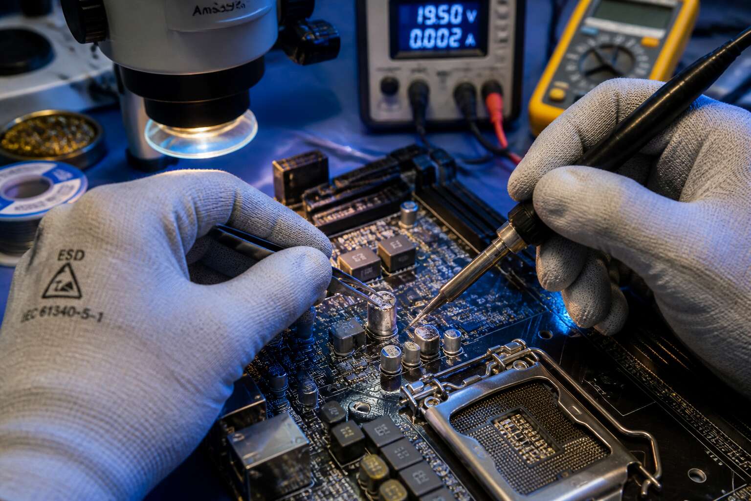
Common Causes of Mainboard Failure
Electrical Surges and Power Supply Damage
A single lightning surge can send thousands of volts through your home’s wiring. That energy often ends up in your computer’s mainboard, destroying microchips and leaving the system dead. Surge damage is a leading reason people seek motherboard repair in South Africa.
Power supply damage is quieter. A degraded PSU produces voltage ripple that erodes capacitors gradually. I have seen boards where the traces literally lifted from the PCB. Over time, the mainboard becomes unstable, leading to random freezes and boot failures. The sources of such stress vary:
- Lightning strikes on nearby lines
- Grid switching during load shedding
- Faulty appliances sharing the same circuit
Overheating and Thermal Stress
Heat damages every mainboard eventually. In South Africa, where summer temperatures routinely push past 35 degrees Celsius, thermal stress is a daily reality. Overheating causes microscopic cracks in solder joints through thermal cycling. Each power-on and power-off expands and contracts the board, breaking connections that were once solid.
Dust compounds the problem by trapping heat around voltage regulators and the chipset. I have seen boards where the PCB warped from prolonged exposure. Capacitors bulge, traces delaminate, and the system fails intermittently before dying completely.
Common contributors to overheating:
- Blocked ventilation from poor case placement
- Failed chassis fans
- Dried-out thermal paste between the CPU and its cooler
Thermal damage is progressive. When the first signs of instability appear, seeking professional motherboard repair can prevent a total loss.
Physical Damage and Bent Pins
In my years of repairs, I have seen more mainboards ruined by clumsy hands than by faulty PSUs. A dropped screwdriver can gouge a PCB trace. A misaligned CPU cooler can crack the laminate. Bent pins cause failures that are easy to miss.
Most sockets use delicate pins that bend under slight pressure. Once a pin folds, a memory channel or PCIe lane may stop responding. LGA sockets, where pins sit on the motherboard itself, are particularly sensitive. Every insertion needs steady pressure.
Physical damage is not always visible. You might see:
- A bulging backplate after overtightening.
- Corrosion from spilled coolant.
- A scratched surface from careless swaps.
These issues rarely show clear symptoms. The system fails to boot or crashes under load. A professional motherboard repair can often restore a board with a single bent pin. A simple motherboard repair often proves sufficient when the issue seems small.
Capacitor Bulging and Leaking
One swollen capacitor can stop a functioning computer from booting at all. These components filter power and smooth voltage, but when internal electrolyte dries out, pressure distorts the metal casing. Leaking fluid then spreads across the board and corrodes nearby traces. I have seen a single bulged cap produce random crashes across an entire system.
Visual checks reveal the damage easily. Common signs include:
- A domed or cracked top.
- Sticky brown residue around the base.
- Discoloured or lifted solder joints.
Random shutdowns and boot loops often trace back to these failures. A professional motherboard repair replaces the faulty capacitors, restoring stable behaviour!
Diagnosing Hardware Issues Without Professional Tools
Visual Inspection Techniques for Burn Marks and Corrosion
A scorched trace on a circuit board often tells a story louder than any diagnostic tool. Without expensive gear, your eyes remain the first line of defense. Begin by examining the board under bright, angled light. Burn marks appear as dark brown or black splotches, sometimes with a faint smoky residue. Corrosion shows up as a pale green or white powder, especially around battery contacts and edge connectors.
Use a magnifying glass to inspect these trouble zones:
- Power input sockets and regulator circuits.
- Mounting holes and standoff points.
- Solder joints near heat sinks.
Catching these signs early can save a motherboard repair from turning into a full replacement. Trust your eyes before you reach for a multimeter.
Power-On Self-Test Beep Code Interpretation
The first sound your computer makes tells you more than any error message ever will. The POST beep code is that message, a series of audible signals your motherboard uses to announce faults before the display even lights up. In South Africa, where many technicians work without oscilloscopes or logic analyzers, these beeps become a primary guide for motherboard repair.
Most boards follow a familiar pattern. One short beep signals a clean start, while long and short tones point to memory, graphics, or CPU faults. The rhythm matters more than the pitch.
- Continuous short beeps point to power supply instability.
- One long beep followed by two short ones indicates a video card failure.
- Repeated long beeps often mean a memory module has failed.
In my experience, decoding these patterns takes patience. You listen, you interpret, and you act. Effective motherboard repair often begins with this exchange, no soldering iron required.
Using a Multimeter for Basic Voltage Checks
On South African repair benches, a R200 multimeter sometimes outperforms an expensive oscilloscope. That tool unlocks motherboard repair when logic analyzers sit idle. The board’s electrical values appear as concrete voltage readings. A digital multimeter set to DC volts reveals whether the 5V standby rail is alive or the 3.3V rail has sagged.
Check the power supply’s connections first. The ATX connector contains a set of expected voltages. Test the purple wire for 5V standby and the orange wires for 3.3V. A short circuit on any rail pulls these readings down. Measure resistance to ground to trace the fault. Motherboard repair without a schematic becomes a method of elimination.
Use the multimeter to confirm CPU core voltage at the VRM. Common checks include:
- Memory voltage near the DIMM slots.
- PCH always-on voltage.
- PCIe slot power pins.
These readings show whether a missing phase is the culprit. The multimeter turns guesswork into informed decision making.
Isolating Memory, CPU, and Peripheral Failures
Statistics from local Johannesburg repair benches reveal a stubborn truth: nearly half of all temperamental machines are abandoned because a memory fault whispered while the CPU bore the blame. Isolating memory, CPU, and peripheral failures demands a deliberate sequence of subtraction, not exotic oscilloscopes. Power off the board, pull every expansion card, and disconnect all drives. Reseat the memory sticks one at a time, then listen for the POST pattern. A silent boot after removing one module often points to a dying DIMM. For CPU suspicion, strip to the bare socket and observe the fan response; modern boards hesitate differently when a processor refuses to initialize. Peripheral issues only surface after the OS loads, so test each USB port with a known good keyboard and mouse.
- Disconnect every peripheral device.
- Boot with a single RAM module in the primary slot.
- Swap the CPU only if a spare lies within reach.
This method of elimination costs nothing but patience, yet it yields exact answers without a bench full of hardware. When the system posts with one DIMM and rejects another, you have already narrowed the motherboard repair to a suspicious channel or socket, saving both time and rands.
Testing the Power Supply Unit First
Most motherboard repair jobs never actually start with the motherboard. They start with a dull hum from a power supply that has seen too many Johannesburg thunderstorms. Load shedding does not help. The constant power cycling stresses the unit’s internals in ways that standard component failures cannot replicate.
Testing the PSU first is cheap and requires zero specialised tools. A paperclip and a multimeter are enough to determine if standby power exists. Unplug everything from the board. Identify the 24 pin ATX connector. Short the green wire to any black wire. The fan should spin. If it does not, you have your culprit. Even better, measure the orange wires first, then the red wires, and watch for sagging voltages beyond the five percent tolerance.
1. Disconnect all cables from the motherboard and drives.
2. Jumper the green and black wires on the 24 pin connector.
3. Check for fan spin and stable voltages across the rails.
A weak PSU starves the board of the exact voltages that capacitors and VRMs require. The result mimics a dead CPU and a shorted USB hub at the same time. Rule out the power source first, because every other diagnostic step depends on that initial juice being clean and stable. This approach alone prevents countless wasted hours and unnecessary motherboard repair bills.
Essential Repair Techniques and Best Practices
Safe Disassembly and Component Handling
Safe disassembly demands a steady hand and deliberate motion. I have seen more motherboards ruined by frantic pulling than by actual electrical faults. Begin with a grounded anti-static wrist strap and a non-magnetic, precision screwdriver set. Clear a dedicated workspace where components can rest without rolling away. When lifting the board from its chassis, use a crisscross screw pattern to release pressure evenly. For stubborn connectors, apply a gentle rocking motion rather than sheer force.
Delicate chip sets and capacitor legs respond poorly to metal tools. A plastic spudger and ceramic tweezers offer control without scarring the PCB. Hold the board exclusively by its edges, as skin oils accelerate corrosion on contact pads. The CMOS battery sits in a frail clip; depress it carefully.
1. Disconnect all power sources and peripheral cables.
2. Remove expansion cards before loosening standoffs.
3. Slide the board toward the rear I/O panel to free it.
A static-free mat under the assembly serves as your safety net. In Cape Town’s coastal humidity, condensation on tools becomes a hidden hazard, so wipe them dry first. Proper handling here prevents issues that no soldering iron can fix later.
Cleaning Corrosion with Isopropyl Alcohol
Corrosion hides beneath components where no visual inspection reaches. Isopropyl alcohol at 90% or higher dissolves the ionic residue that slowly eats copper traces. For motherboard repair, this step often determines whether a board lives or dies. I have seen a board return to normal operation after a careful soak.
Apply the alcohol with a soft brush, working from the center outward. Let it evaporate completely before powering anything. A second pass with distilled water neutralizes stubborn oxidation. Do not use an ultrasonic cleaner unless the board is stripped entirely bare.
Keep these rules in mind:
- Use only 90% or higher isopropyl alcohol without additives.
- Avoid cotton swabs; they shed fibers that trap moisture.
- Work in a ventilated area to prevent fume buildup.
Replacing Faulty Capacitors with Soldering Iron
Replacing a bulged capacitor demands precision. A soldering iron set to 350 degrees Celsius loosens the joints without scorching the board. I always grip the component with tweezers and apply gentle torsion while heating each pad. The old part lifts cleanly, leaving through-holes open for the replacement.
Match the capacitance and voltage rating exactly. Polarity matters, so align the stripe with the board markings. Clean the area with alcohol before soldering. For best results, use a chisel tip and fresh leaded solder.
- Heat both pins alternately to avoid damaging the trace.
- Let the solder flow into the via, not just around the pin.
This fix resolves random crashes and power instability. Mastering it elevates your motherboard repair skill set.
Resoldering Cracked Solder Joints
Cracked solder joints are the silent killers of otherwise healthy motherboards. They masquerade as memory errors, random freezes, or that dreaded system that powers on only when it feels like it. The root cause is usually physical stress or thermal cycling, where the constant expansion and contraction of components eventually fractures the solder connection. It is not always visible to the naked eye, which makes it a frustrating diagnosis for anyone starting their journey in motherboard repair.
The classic symptoms are intermittent and often temperature dependent. A board that works perfectly when cold but fails after running for an hour points directly at a hairline fracture within the PCB solder. When you suspect this, the first step is to identify the stress points.
- Check CPU socket retention brackets for flexing
- Inspect PCIe slot anchor points for movement
- Look for heavy heatsinks or components that lack support
- Examine the backside of the board for micro-fracture lines
Resoldering these areas requires a steady hand and a hot iron, around 380 degrees Celsius. Apply fresh flux generously to the suspect joint, then reheat it until the solder flows freely and wets the pad completely. I always add a small amount of new solder to guarantee a solid bond. The result is a renewed connection that withstands the mechanical strain. This technique is non-negotiable for long term stability, and it separates a proper repair from a temporary bandage. Mastering this precise action is the difference between a resurrected board and a paperweight in your shop. Sustained practice here ultimately sharpens every other aspect of your motherboard repair toolkit.
Repairing Traces with Jumper Wires
A fractured trace can hide under a pristine solder mask, leaving you with a dead board that passes every voltage test. This is where jumper wires become the essential repair technique. In my experience, mastering this skill elevates your motherboard repair skills more than any other single method.
Scrape the mask away to expose copper on both sides of the break, then tin each pad. Use 30 AWG wire to bridge the gap. A multimeter confirms the connection before you reassemble anything.
- Anchor the wire at both ends with solder
- Use hot glue to prevent strain
- Test for shorts after power-up
Each trace repair sharpens your eye for board defects. That precision carries into every future job you take on.
Updating BIOS to Resolve Boot Issues
A board that powers on but refuses to boot often hides its fault in the firmware layer. Updating the BIOS resolves failures that no soldering iron can reach. I have watched a single flash resurrect a motherboard that had passed every voltage test and still sat dead. For anyone practising motherboard repair, this step deserves a place in the standard workflow.
The procedure is short but unforgiving. Download the exact BIOS revision from the manufacturer, then match the board model and revision number precisely. Format a USB drive as FAT32 and drop the file in the root directory. Enter the BIOS menu, or use the flashback port if the board will not POST. Keep power stable throughout. A UPS matters in South Africa where load shedding can strike mid-flash and brick the board permanently!
A corrupted BIOS shows no burn mark and no bulging capacitor. The board simply refuses to hand control to the operating system. Updating the firmware takes minutes, costs nothing, and turns an apparent paperweight back into a working system. Few techniques in motherboard repair deliver such a dramatic result for so little effort.
Advanced Component-Level Fixes
Replacing the Chipset or Southbridge
Many technicians shy away from chipset replacement, yet it is sometimes the only viable path. The southbridge handles low speed peripherals, so a failure there cripples USB and SATA ports. This motherboard repair demands precision hot air rework and a steady hand.
Before attempting, confirm the failure. Measure voltages at the chipset, check for shorts to ground. If the chip is truly dead, order a compatible donor. Use a preheater to avoid warping the board, then carefully lift the old chip with controlled heat.
- Clean the pad array with braid and flux
- Align the new chip using the board’s silkscreen
- Apply even heat and let the solder reflow naturally
After cooling, test with a multimeter before reassembly. This level of work separates serious hobbyists from casual tinkerers, and it elevates any motherboard repair project.
Reflowing Graphics and Memory BGA Chips
Reflowing graphics and memory BGA chips is a ritual of measured desperation. One careless heat pass can turn a salvageable board into a corpse. Yet when artefacts bloom across the screen or memory training fails post, this motherboard repair step is the last exorcism.
The trick is controlling thermal gradients. A preheater beneath, a hot air nozzle above, and a thermocouple to watch the curve. You want the solder balls to melt just enough to reconnect, not liquefy and bridge. Some technicians swear by flux and a prayer. I prefer measured dwell time. Watch the chip settle, that tiny drop, then back off the heat. Let it cool slowly to avoid cracked interconnects.
If you see:
- Warped substrate
- Burned PCB
- Persistent shorts
Stop. Reflow is not a miracle. It is probability management.
Bypassing Failed Power Regulation Circuits
Most power regulators die without drama. One day the rail reads 1.8 volts, the next it reads zero. When that happens, you can attempt an advanced bypass. This technique involves feeding clean voltage directly to the load, skipping the dead circuit entirely. It is not for beginners. You need to trace the failed component, understand the required current, and solder a jumper wire with precision.
- Confirm the load has no short circuit.
- Select a regulator with adequate current rating.
- Use a fused supply for your test connection.
I prefer bypassing when the replacement part is unavailable. You lose features like soft-start or overcurrent protection. That might be acceptable for a test bench, but risky for a daily driver. The trick is knowing when to stop. A successful bypass feels clever. A failed one leaves a burning smell. In the end, every motherboard repair comes down to honest probability.
Post-Repair Validation and Long-Term Reliability
Stress Testing with MemTest and Prime95
Once the soldering iron cools and the replacement components sit flush, the real work begins. A repaired board that posts once can still fail under sustained load, so I always push past the initial excitement of a successful boot. This phase is where marginal repairs reveal themselves, often through intermittent crashes that surface only after hours of operation.
Memory stability is the first gate. I run MemTest86+ for at least eight passes, which forces every address line through its paces. If any error appears, I recheck the socket and trace continuity rather than swapping RAM, since the fault usually lives in the motherboard repair work itself. Clean errors across multiple passes give me confidence that the memory bus handles stress without degradation.
After memory passes, I move to Prime95 with a blended torture test. This stresses the CPU, memory controller, and voltage regulation circuits simultaneously. A board may boot fine but show instability when the CPU pulls maximum current. I monitor for worker threads stopping or system lockups, which point to weak solder joints or insufficient cooling around the repaired area. I typically run this for six hours to catch thermal drift.
For boards that show promise, I use a structured validation sequence:
- Twenty consecutive warm reboots to test boot loop resilience
- Three hours of Prime95 small FFTs to stress the CPU cache and core voltage
- Two hours of FurMark combined with Prime95 to stress the power delivery system
- An overnight soak test at elevated ambient temperature to catch intermittent faults
These steps separate a functional repair from a durable one. I also log every temperature reading during the stress phases. A sudden spike above expected values often indicates a failing component that only reveals itself under prolonged thermal load. Catching this during validation beats a field failure weeks later.
Long-term reliability comes down to how the repair holds up across thermal cycling. The expansion and contraction of the PCB can crack a marginal solder joint that passed initial testing. I let the board cool completely between stress tests, then restart the cycle. This thermal shock mimics real-world usage patterns where a machine shuts down overnight and boots again in the morning.
Thermal Imaging to Detect Hotspots
A thermal camera exposes what software stress tests cannot. A board that survives Prime95 can still carry a hidden hotspot, a single component drawing excess current through a weak solder joint. I scan the entire PCB after each validation round, hunting for temperature deltas beyond five degrees from the surrounding area. The power delivery section gets the closest look, since voltage regulators often reveal the earliest signs of degradation.
This thermal pass adds minutes to any motherboard repair, yet it catches faults that would otherwise surface weeks later. Uneven heat distribution across the board points to cracked traces or failing BGA connections. A component that runs hot while its neighbours stay cool tells me to inspect that zone again, reflow the joint, or replace the part entirely. Thermal imaging turns long-term reliability from an assumption into a measurable outcome, and that clarity is worth every second of the scan.
Reassembling and Cable Management
Silence settles on the bench. The thermal scan has passed. Now the board returns to its chassis, but this is not a careless act. Post-repair validation extends beyond the test bench. The final assembly is a precise act. I check each mounting point, each standoff, each torque.
- Confirm the I/O shield sits flush.
- Verify the CPU cooler bracket has even pressure.
- Reconnect every fan header to the correct zone.
Cable management is not aesthetics; it is physics. A stray SATA cable can choke airflow, or worse, rest against a hot VRM. I route every line with intent. The power connector, the front panel headers, the fans. Each cable has a path. For any motherboard repair, the reassembly is the final test. Before I close the case, I run one last power-on. The fans spin, the POST code cycles, and the system holds steady. This is the true measure of long-term reliability. The motherboard repair is complete, but the watch continues. The first week of operation is the quiet verdict.
When to Recommend a Replacement Board
The first week after a motherboard repair tells the truth! Around 15% of repaired boards fail again within a month when underlying issue was not visible damage. Validation extends beyond the simple POST. I monitor for intermittent resets, odd fan curves, and memory errors under load. Thermal cycling from South Africa’s load shedding stresses solder joints.
This is why I keep a diagnostic log for every unit. When a repair holds for seven days, the odds shift in your favour. But sometimes the board does not recover. The decision to replace requires honest criteria:
- Repeated failures in the same voltage rail
- Delaminated PCB layers around mounting holes
- Corrosion that has migrated under the BGA package
- Cracked traces that reappear after flex testing
These signs signal that motherboard repair has reached its limit. The cost of a second repair exceeds a replacement board. Long-term reliability depends on knowing when to stop.
0 Comments