
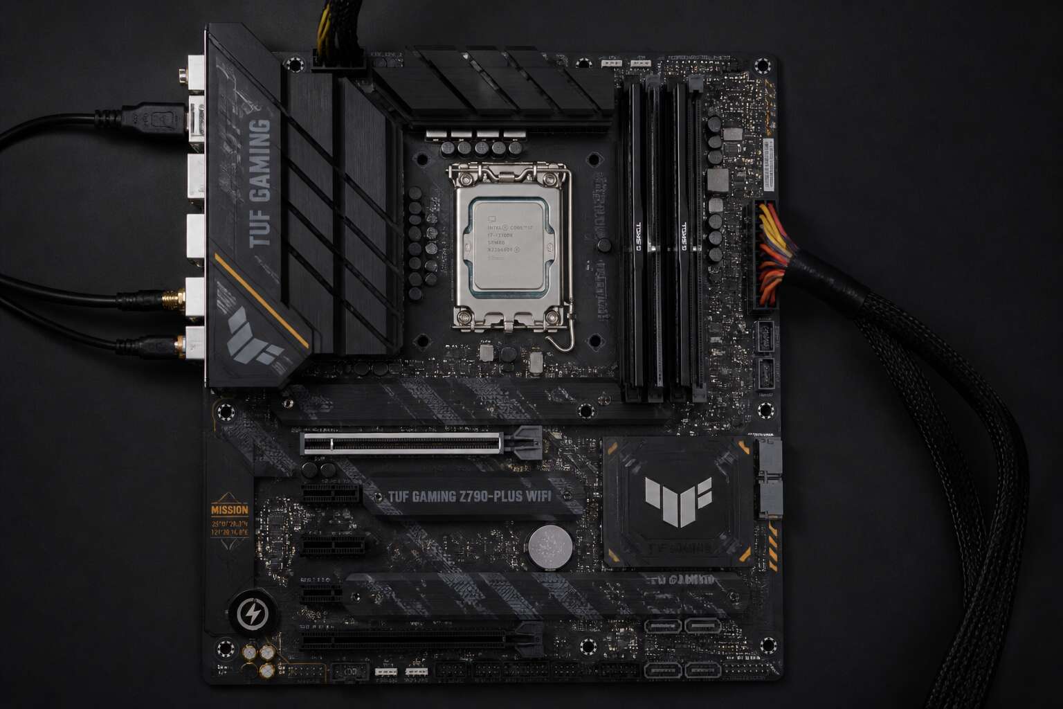
Processor and Memory Interfaces
CPU Socket
Nothing humbles a PC builder faster than a bent CPU pin. The socket is the gatekeeper between your processor and the rest of the system. Memory interfaces, those long DIMM slots, are equally fussy. They expect specific modules in specific orders. This is where motherboard parts and functions stop being textbook theory and start affecting your wallet.
Before you commit to a purchase, check the basics:
- Socket generation and manufacturer
- RAM type, speed, and maximum capacity
- Number of memory channels
Mismatching these components produces a system that simply refuses to boot. I have watched seasoned builders install DDR4 into DDR5 boards. The results were not pretty. The socket also sets your upgrade ceiling, so a little research now prevents a full rebuild later. Understanding motherboard parts and functions helps you avoid these headaches, because every pin and slot has a job, and they do not tolerate improvisation.
RAM Slots
RAM slots are a lesson in patience. Most consumer boards present four DIMM slots, yet populating all four rarely delivers a performance gain. The memory controller governs these interfaces, and it prefers specific configurations. Your manual will label them A1, A2, B1, B2. The invisible rule: fill the second and fourth slots first. That simple act unlocks dual channel operation. Most builders ignore the labels and suffer the consequences.
- Two modules in the right slots give you dual channel speed.
- Four modules may force your controller to lower frequencies.
- One module leaves bandwidth on the table.
Motherboard parts and functions determine this behavior. Matching RAM capacity and speed across slots prevents stability issues. The BIOS reads the SPD chip on each module to set timings automatically, but only if the board can identify the correct slots. When you understand these motherboard parts and functions, you stop guessing and start building systems that boot first try.
Chipset
Every motherboard hides a quiet bureaucrat beneath the heat spreader. The chipset, that busiest of middle managers, negotiates every connection your CPU refuses to touch. RAM and graphics get direct lines to the processor; everything else reports to the chipset. Give it too much work, too many SATA drives and M.2 drives and USB devices all demanding attention at once, and you will discover the limits of the DMI link. Motherboard parts and functions become clearer when you read the block diagram, not the glitzy product page. The chipset also determines which connections share bandwidth, so check the fine print:
– Chipset M.2 shares the DMI link with other peripherals
– CPU M.2 receives a private PCIe lane
– Extra SATA ports often disable PCIe slots, so plan accordingly
Respect those paths and you avoid building a machine that stutters during a busy export. Motherboard parts and functions reward the prepared.
Expansion Slots
A CPU with twenty PCIe lanes forces a conversation about priorities. Every expansion slot, M.2 drive, or network card you add consumes a slice of that finite resource. Motherboard parts and functions reveal themselves through these lanes. The first x16 slot typically enjoys a direct connection to the processor, while secondary slots often route through the chipset, sharing bandwidth with everything else. Memory interfaces work similarly. The memory controller lives inside the CPU, and the motherboard merely extends those traces to the slots. If you populate all four DIMM slots, the controller may drop speed to maintain stability. Understanding these pathways prevents the heartbreak of a graphics card running at half its potential.
BIOS/UEFI Chip
When Johannesburg load shedding dims the lights, your PC’s behaviour changes in ways that reveal the true nature of motherboard parts and functions. The processor’s memory controller sits inside the CPU die, not on the board itself. What the motherboard provides is the physical pathway, the traces etched between the DIMM slots and the socket. Populating all four memory slots forces that controller to work harder, often dropping from 3200MHz to 2666MHz to maintain stability. This is not a flaw, it is physics. Every additional rank of memory adds electrical load, and the controller must compensate.
The BIOS and UEFI chip, that small flash memory module, holds the initial instructions. It initialises the memory controller, sets voltages, and determines which drive boots first.
Basic things you will find in a modern UEFI:
– XMP profiles for memory overclocking
– Boot priority and secure boot settings
– Fan curves and temperature thresholds
– Storage configuration and RAID arrays
South African users dealing with inconsistent power should pay attention to the BIOS version. Updates often fix memory compatibility and improve power delivery behaviour. The motherboard extends the processor’s connections, but the UEFI decides how those connections are used. Understanding motherboard parts and functions means respecting this firmware layer. A graphics card in a secondary slot may run at reduced lanes, but the UEFI’s configuration of those lanes determines the actual bandwidth available.
Power Distribution Components
24-Pin ATX Connector
Press the power button on a desktop in Johannesburg or Cape Town, and the first component to stir is the 24-Pin ATX Connector. This port, usually located along the right edge of the board, receives raw current from the power supply and distributes it across the entire system. In a country where loadshedding interrupts the grid, the orderly transfer of energy inside your machine becomes a quiet reassurance.
The connector carries several voltage lines to different motherboard parts and functions:
- +3.3V for the chipset and other low-power logic
- +5V for legacy peripherals and USB circuits
- +12V for the CPU voltage regulator and expansion slots
Each pin is keyed to prevent incorrect insertion. The 20+4 pin design allows compatibility with older boards while keeping modern systems powered. This single connector feeds every other subsystem on the board.
8-Pin EPS Connector
Press your ear to a running machine and you might hear the faint whine of the 8-Pin EPS Connector working. That plug, seated next to the CPU socket, handles what the 24-Pin ATX Connector cannot: raw 12V current for your processor. It is a narrow channel between power supply and motherboard, yet its failure is absolute.
I have seen systems that refuse to post simply because this connector lost its grip! The engineering is direct:
- Four 12V pins carry the main CPU feed
- Four ground pins complete the circuit
- Some designs add a fourth 12V pin for extreme loads
Understanding these motherboard parts and functions matters when you troubleshoot a dead system. The EPS connector is not glamorous, but it is inseparable from a working PC.
Power Delivery Phases
A system only hums to life when raw power transforms into something a processor can trust. The power delivery system is the quiet negotiator, translating chaotic energy into precise action. I have traced countless failed builds back to this very stage, where a slight oversight becomes a permanent silence.
The Voltage Regulator Module, or VRM, performs this alchemy. It sits near the CPU socket, and its components, the chokes, the capacitors, and the MOSFETs, each carry a specific responsibility.
– Chokes filter the power flow, smoothing out any rough edges.
– Capacitors hold charge and release it instantly when the processor demands a sudden burst of performance.
– MOSFETs act as high-speed switches, regulating the voltage output with precise timing.
These elements arrange themselves into what we call power delivery phases. A single phase is one complete circuit that can manage a steady stream of current. A motherboard with six phases shares the workload across six separate circuits, reducing heat and strain on each individual component. This directly influences how many cores you can run at full frequency. I remember a system with a simple four phase design that struggled to feed a high core count CPU. The result was an unstable overclock and a perplexing boot loop. The architecture of power delivery, often overlooked in the discourse on speed, is the true foundation of stability. Every point where current flows, every phase that responds to a sudden load change, it is all part of the integrated system. These motherboard parts and functions are the unseen labourers. They translate a wall socket’s raw power into the finely tuned voltages that logic itself can use. When you push a system hard, you are testing the honesty of this physical design, not just the silicon cleverness above it. A failure here renders every other component useless, no matter how advanced.
Capacitors and Chokes
A processor can demand a surge of current in microseconds. Capacitors and chokes make sure that request doesn’t end in a crash. Capacitors, those cylinders clustered near the socket, store charge for sudden load changes. Their quality comes down to equivalent series resistance. Lower ESR equals less heat and steadier voltages. Chokes, often shaped like cubes, are inductive coils that smooth current by resisting abrupt swings. The two work together to suppress electrical noise before it reaches the CPU.
When inspecting a board, I choose solid polymer capacitors over older electrolytic types. They handle heat better, a genuine advantage in South Africa’s ambient temperatures!
Capacitor count and choke quality tell you a lot about a motherboard’s overall strength. These motherboard parts and functions decide if your system remains calm or randomly reboots mid-task. Understanding basic motherboard parts and functions is the difference between a reliable rig and an expensive failure.
Connectivity and Expansion Interfaces
Rear I/O Panel
Most builders treat the rear I/O panel as an afterthought, yet this steel bracket determines which cables your setup can accept. The motherboard parts and functions here center on connectivity and expansion interfaces that link your internal components to the outside world.
USB ports dominate the panel, ranging from USB 2.0 to USB 4. Ethernet jacks provide wired networking with speeds up to 10 Gbps. Some boards include Wi-Fi antenna connectors, while others offer coaxial S/PDIF audio.
- USB-A and USB-C ports
- RJ45 Ethernet port
- Audio jacks for speakers and microphones
- HDMI or DisplayPort video outputs
The arrangement of these ports varies by manufacturer, but the function remains consistent. I always check the rear I/O panel before buying a motherboard because it dictates which peripherals I can use without adapters!
Front Panel Headers
The front panel headers are the quiet negotiators of the motherboard parts and functions. Most builders focus on the spectacle of a GPU, but these tiny pins manage the daily rituals of powering on and resetting your system. When you press the case button, the signal travels here first, a cascade of energy that breathes life into the CPU and RAM. It is a transaction of intent between you and the machine.
Beyond the basic power switch, these headers speak to the case’s soul. They carry the language of activity LEDs, the rhythmic blinking that tells you the storage is working. Audio headers route the front jack sound, connecting your headphones to the chipset’s digital stream. Modern cases also use USB-C and USB 3.0 headers for high-speed front ports, a necessity for fleeting data transfers.
To understand the physical layout, consider what typically resides there:
– Power and reset switch pins
– Power and HDD LED pins
– Front panel audio connector (HD Audio)
– USB 2.0 header
– USB 3.2 Gen 1 header
Connecting these requires reading the manual’s diagram. A reversed polarity on an LED often simply means no light, a benign failure. Yet, a misplaced power switch jumper is a dead system, a stark reminder of the precision inherent in all motherboard parts and functions. This small grid of pins represents the convergence of human habit and electrical logic, the tangible bridge you touch every day to start your digital life, from Johannesburg to Cape Town.
USB Headers
Most builders ignore USB headers until something stops working. These internal connectors link your case’s front ports to the motherboard, feeding data and power through distinct pin layouts. Recognizing them is part of learning motherboard parts and functions, since they determine which front ports operate.
Common header types include:
- USB 2.0 header, four pins for two ports
- USB 3.2 Gen 1 header, nineteen pins for high speed
- USB-C header, for reversible cables
The physical layout matters in daily use. A misplaced USB 3.2 header will not fit into a USB 2.0 socket, saving you from error. In Cape Town offices, this simple geometry keeps data moving.
M.2 Slot
The M.2 slot is the narrowest part of modern motherboards, yet it delivers the fastest storage speeds available. A single NVMe drive in this interface can read data at over 7,000 MB/s, far beyond what SATA cables allow. This compact connector also hosts Wi-Fi cards and Bluetooth adapters, saving you from adding extra PCIe cards.
When you shop for a board in Johannesburg or Cape Town, check the M.2 key type. Most drives use the M key, while Wi-Fi cards often use the E key. The physical notch prevents you from installing the wrong device.
- Key M: NVMe SSDs with PCIe lanes
- Key E: Wireless networking cards
- Key B+M: SATA-based M.2 drives
Understanding these details is part of mastering motherboard parts and functions.
SATA Ports
Most PC builders ignore SATA ports until they run out. These connectors handle drives that don’t need PCIe speed. A single SATA III channel tops out at 600 MB/s, which works fine for mechanical hard drives and optical media. The port layout is simple, but knowing the limits helps. Devices that still rely on SATA:
- Mechanical hard drives
- 2.5 inch SATA SSDs
- Optical and Blu-ray drives
Each port pairs with a separate power cable from the PSU. Most boards include four to six SATA headers, so plan ahead if you run a media server in Durban. SATA also supports hot swapping, letting you remove a drive while the system runs. Understanding motherboard parts and functions means knowing when SATA makes sense over M.2.
PCIe x16 Slots
The PCIe x16 slot is the most important connector for performance. It feeds your graphics card with data, and bandwidth matters. A PCIe 4.0 x16 slot can move about 32 GB/s in each direction. That is enough for current GPUs and newer SSDs. However, not every x16 slot runs at full x16 electrical speed. Some boards share lanes with other parts, which reduces throughput. Check your motherboard manual before adding multiple GPUs.
Items that commonly occupy the x16 slot:
– Graphics cards
– High speed network adapters
– RAID controllers
Studying motherboard parts and functions means understanding how these lanes are distributed. A second x16 slot might run at x4 mode. That is fine for a network card but poor for gaming. If you run a rendering workstation in Cape Town, plan your lane usage carefully. The slot looks big, but its true speed is not always what the label claims. That is the kind of detail motherboard parts and functions cover.
Form Factors and Layout Features
ATX
When a motherboard is described as ATX, the label refers to its physical form factor and the layout features that define its footprint. Intel introduced this specification in 1995, fixing the board’s dimensions at 305mm by 244mm. That footprint governs which chassis can house it, so the placement of motherboard parts and functions must align with the case’s standoff positions. A mismatch here means mounting holes simply will not line up.
ATX layout features also shape thermals. The CPU socket sits high, away from expansion cards, allowing heat to rise and channel toward the rear exhaust. A standard nine-hole mounting pattern keeps the board level, preventing flex that can crack traces when heavy graphics cards are installed.
- A nine-hole standoff pattern matches every ATX case tray
- The rear I/O shield dimensions are fixed across the standard
- Board corner radii and mounting points follow a shared template
Micro-ATX
Micro-ATX arrived in 1997 and remains the most widely stocked board format in South African retail stores. The square 244mm by 244mm footprint cuts the depth of a full ATX board while keeping the same rear edge dimensions, so the two formats share a familiar layout.
What changes is the density. Motherboard parts and functions sit closer together, which means the 24-pin connector moves further inward and the chipset sits nearer the rear I/O. The four mounting holes along the back edge align with ATX case trays, so swapping between board sizes usually requires no new chassis.
Key layout points:
– Four expansion slots instead of seven
– Same rear I/O panel width as ATX
– Front standoff positions vary between manufacturers
Mini-ITX
Mini-ITX condenses the motherboard down to a 170mm square footprint. This forces a complete rethink of how motherboard parts and functions occupy space. The board retains the standard rear I/O panel width, yet every connector shifts closer to the socket. The 24-pin header moves to the top edge, while SATA ports angle sideways.
Personally, I find this layout demands more patience than skill. You often install the CPU cooler before the RAM, or vice versa. Three standoffs match standard ATX trays, so most cases fit without new brackets. Understanding the arrangement of motherboard parts and functions is essential here.
- One expansion slot, usually at the topmost position
- Two DIMM slots for dual channel memory
- One M.2 socket routed directly to the chipset
The result rewards careful component ordering, not component count.
Mounting Holes
Mounting holes reveal their purpose before you slot a component into place. These brass-lined apertures anchor the board to the chassis and determine which cases accept which format. Standard ATX trays use nine standoff positions, though some boards only require six. Micro-ATX shares the top four holes with ATX, which is why most enclosures handle both formats without extra brackets. Mini-ITX takes three of those positions, usually the upper-left, lower-left, and lower-right. You can trace motherboard parts and functions by looking at these holes alone.
Consider the pattern you actually need:
- Verify standoff positions match your case tray before assembly
- Count mounting holes against the manual, since some boards include dummy holes
- Check for tool-free clips around the standoffs, they speed up later upgrades
The positioning of each hole governs which motherboard parts and functions fit your build, so measure twice and mount once.
Standoff Positions
The physical negotiation between case and board happens at the standoff positions, a silent agreement of geometry that dictates which motherboard parts and functions you can ever hope to install. This layout is the first true constraint, a fixed map that either liberates your component choices or quietly limits them. It forces a decision before you even hold a screwdriver, demanding you reconcile your desired performance with the physical reality of your chosen chassis.
For ATX, the standard nine-position tray is the most common arrangement, but some boards ship with only six populated holes, relying on the tray for the rest. Micro-ATX shares the top four positions with ATX, so it drops into most towers without issue. Mini-ITX, with its three-hole pattern, feels almost sparse, yet it occupies the same upper-left, lower-left, and lower-right coordinates, which is why a single mounting point can make or break a small form factor build.
– Verify the standoff pattern against your case manual before you start, as mismatches cause short circuits.
– Count the populated holes against the board’s manual, since some positions are dummy holes for alternate trays.
– Look for tool-free clips near the standoffs; they turn a ten-minute install into a two-minute task.
The arrangement of these holes ultimately defines which motherboard parts and functions you can physically access, so measure the tray twice and mount once.
0 Comments