
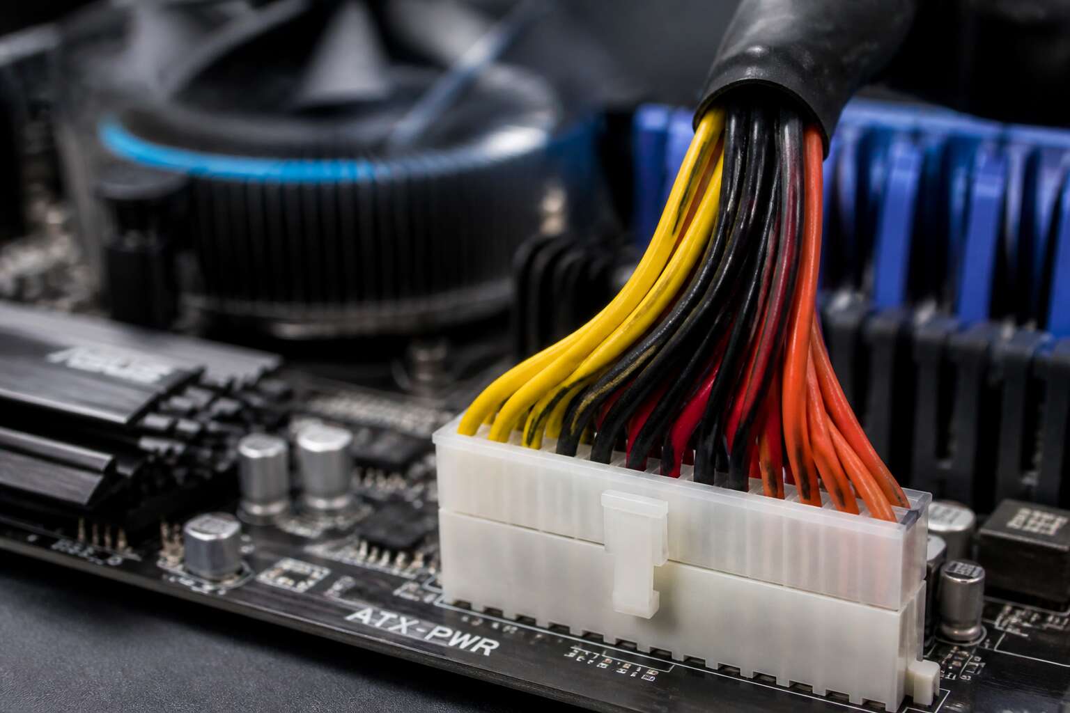
The Role of the Main Power Connector
Delivering Sufficient Power
The main power connector acts like a strict traffic cop for electricity, but it actually enforces the speed limit. Understanding the motherboard 24 pin connector pinout matters because this single plug carries +3.3V, +5V, and +12V rails to every hungry component. Without sufficient amperage flowing through these pins, your CPU stutters, RAM throws errors, and the system restarts for no apparent reason. Here is what this connector really handles:
- Load balancing across multiple voltage rails
- Ground return paths for stable current flow
- Voltage sensing that tells the PSU to adjust
The ATX specification expects this plug to deliver hundreds of watts, but only with clean contact on every pin. A bent pin or loose seating in that 24 pin layout can drop voltage dangerously low. Respect the pinout, and your machine runs smooth. Ignore it, and you will learn more about troubleshooting than you ever wanted.
Connector Evolution
The motherboard 24 pin connector pinout is a covenant. Every time you press the power button, the main power connector carries the entire electrical load. I have seen systems fail to start because this connector was not fully seated. That is the role: to be the physical foundation for all power delivery.
Connector evolution followed necessity. The original 20 pin design lacked the extra +12V and ground pins that modern CPUs demand. When ATX 2.0 arrived, the extra four pins gave engineers headroom for lower impedance and cleaner voltage. Consider the shift:
- 20 pin for Pentium 4 era
- 24 pin for multi-core and PCIe
- ATX12VO for future efficiency
Each iteration reduced resistance. The pinout adapts, but the role remains constant: deliver without drama! That is why we study the pinout before we touch a single wire.
Common Identification Methods
The main power connector is the first point of contact between the power supply and the system board. Its role extends beyond simply carrying current; it establishes a common ground and distributes the 3.3V, 5V, and 12V rails to the appropriate bus structures. Understanding the motherboard 24 pin connector pinout allows a builder to trace potential shorts or voltage drops before they become catastrophic. Identification methods are straightforward. You can count the pins, look for the retention clip, or measure the keyed plastic housing. Common methods include: 1. Inspecting the locking tab. 2. Checking for the chamfered corners. 3. Verifying the pin thickness. Each method confirms orientation. A misaligned connector can damage the port. Always match the clip to the socket. That is the practical application of this pinout knowledge.
Detailed Pin Functions
The +5V Standby Pin
The +5V standby pin, often the purple wire in your system, is the quiet guardian of the motherboard 24 pin connector pinout. While other pins deliver heavy current during operation, this one never truly sleeps. It maintains a small, constant trickle of power even when the main rails are silent. That is why your keyboard light stays on or your Wi-Fi card can listen for a magic packet.
In practice, this standby rail serves several critical background tasks:
– Powering the CMOS battery circuit to preserve BIOS settings
– Enabling wake-on-LAN from a full shutdown
– Keeping USB ports alive for charging or input devices
– Supplying the management engine for remote administration
I find it fascinating that such a modest pin enables features we take for granted. When you understand the motherboard 24 pin connector pinout, the standby pin is the difference between a machine that is off and one that is merely resting. Its absence would break the entire power state infrastructure.
The +12V Rails
Each +12V pin in the motherboard 24 pin connector pinout is rated to carry up to 9 amps of continuous current. Most connectors carry two of these pins, usually yellow wires, positioned to distribute electrical load evenly across the connector.
These rails feed the CPU voltage regulator circuitry, which steps the 12V input down to the core voltage your processor demands. The motherboard 24 pin connector pinout allocates these pins specifically because the CPU draws more current than any other component on the board. They also power fan headers and PCIe slot auxiliary circuits.
Here is what the +12V rails support:
– CPU VRM input power
– System fan headers
– PCIe slot power for expansion cards
Without a stable 12V supply, the entire system faces brownouts under load. The motherboard 24 pin connector pinout places these pins centrally so trace lengths remain short and resistance stays minimal.
The -12V and -5V Pins
One of the most overlooked pins in the motherboard 24 pin connector pinout carries negative voltage and does almost nothing. The -12V rail, identified by its blue wire, supplies just 0.5 amps. It survives for legacy serial interfaces and audio codecs that need a negative supply:
- Serial port transceivers
- Integrated audio amplifiers
- Voltage sensing circuits
Most boards draw no measurable current from it, yet removing it would break compatibility with older expansion cards.
The -5V pin disappeared completely. Early ATX revisions supplied it for ISA slots. When that bus vanished, the spec cut the pin entirely. The motherboard 24 pin connector pinout reassigned that contact to reserved functions.
Ground Connections
Ground pins rarely get the spotlight, yet they carry every return current from your board. The motherboard 24 pin connector pinout includes multiple black wires, each serving a specific path for power delivery. Without them, voltage would wander and instability would follow.
The ground pins are all tied together inside the PSU, but their placement across the connector matters. A few responsibilities include:
- Returning current from the +12V and +5V rails
- Providing a low impedance reference for voltage regulators
- Shielding sensitive analog signals from digital noise
This separation keeps noise away from sensitive logic. A simple rule applies: never remove a ground pin. You might think one less is harmless, but these wires complete every circuit. In South Africa’s warmer climate, solid grounding matters even more. The resistance of a long PSU cable can shift voltages, and a good ground connection compensates. That is why the pinout designates specific contacts for this purpose.
Power Good Signal
The Power Good signal takes up to 500 milliseconds to stabilize after power is applied. This is a critical detail inside the motherboard 24 pin connector pinout.
This signal, carried on pin 8, is the PSU’s way of saying that all voltage rails are ready. Without it, the CPU would start executing instructions on unstable power. That could lead to corrupted memory or random crashes.
In South Africa, where grid frequency can waver, this signal is essential. The motherboard holds the reset line active until Power Good is high. This ensures a clean boot sequence. Power Good performs several specific duties:
- Holding the CPU in reset until voltages are stable.
- Providing a clean start signal for the chipset.
Sense and Control Pins
The motherboard 24 pin connector pinout carries more than raw current. It also carries a set of quiet signals. The sense wires travel from the voltage rails back to the power supply. They measure the voltage at the motherboard itself, not at the PSU output. This lets the supply correct for losses along the cable run.
Here are the sense pins found on a standard connector:
- Pin 13 is the +3.3V sense line.
- Some harnesses add a sense conductor for the +5V rail, though this is less common.
Control is a separate matter. The PS_ON signal on pin 16 is the motherboard’s command line. Pulling it low tells the PSU to start. Releasing it tells the PSU to stop. This is distinct from Power Good, which only confirms that voltages are stable.
These pins rarely carry significant current. Yet the motherboard 24 pin connector pinout depends on them for accurate voltage regulation and clean shutdown.
Compatibility and Adapters
20-Pin to 24-Pin Conversions
An older 20 pin PSU can physically connect to a modern board using an adapter, yet the motherboard 24 pin connector pinout demands more. The adapter simply lets extra pins remain unused. Some boards boot fine, others refuse outright. Budget models tolerate the missing four pins; high end boards often do not.
- 20 pin to 24 pin works only if the board’s design accepts missing pins.
- 24 pin to 20 pin is safer, since extra pins simply dangle.
- Check clearance around the socket before installing.
The motherboard 24 pin connector pinout must align with the adapter’s orientation. Misaligned pins can short the board! A reverse adapter offers a cleaner fit for older systems.
Ensuring Polarity and Alignment
One rotated notch is all it takes. The motherboard 24 pin connector pinout assumes a single orientation, and a mismatched adapter turns 5V into a ground rail. The board may power on once, then emit a smell that lingers in the workshop for days.
The latch exists because vibration from cooling fans can loosen connectors. Adapters with flimsy shells sit proud, they wiggle, and they manufacture intermittent shorts. Reinforced shells resist that, and they also keep polarity stable.
- Side-clip adapters match the ATX latch position.
- Center-notch adapters fit boards with alternate keying.
- Straight-through adapters pass every conductor in sequence.
Universal adapters with extra holes in the housing accommodate various keying standards, but those holes also permit wrong insertion. The motherboard 24 pin connector pinout remains identical, regardless of the adapter’s shell design.
Using Extension Cables
Extension cables let you reposition the motherboard 24 pin connector pinout without cutting wires. They work when the original cable is too short for a case with a basement mount. You get a clean routing path, but only if the extension uses the same wire gauge and pin crimps. A poor extension introduces voltage drop under load. The pinout stays identical on both ends, so signal integrity depends on the cable quality. Some extensions include capacitors for noise filtering. Others lack the sense wire continuity. Check these points before buying:
- Confirm the extension is 18 AWG or thicker.
- Verify the sense pins are connected.
- Ensure the latch clicks.
Using a quality extension beats using a permanently shortened cable. It adds flexibility for cable management. Just remember that every connection adds resistance. Keep the total length under 60 cm to avoid instability. That is the practical limit for most ATX supplies.
Mixing with Other Connectors
Most people forget that the motherboard 24 pin connector pinout is not a universal language. Mixing it with other connectors without checking pin maps can fry a board. I have seen adapters that claim to convert a server power supply to ATX, but they often skip the sense pins. That leads to voltage regulation errors.
When you buy an adapter, verify the wiring diagram. A simple mistake, like swapping the +5V standby with a ground, causes permanent damage. The list below shows typical mixes:
– 20+4 pin adapters for older boards
– EPS to ATX adapters for CPUs
– Molex to 24 pin for legacy supplies
Each has quirks. The EPS to ATX adapter is risky because EPS carries four extra grounds. Using it on a modern board usually works, but the pinout must match the motherboard 24 pin connector pinout exactly. Do not assume a standard adapter works for every brand. Check the vendor’s documentation, and always measure continuity with a multimeter before powering up. That habit saves you from costly smoke and dead components.
Troubleshooting Power Issues
Symptoms of Faulty Connections
A flaky connection on the motherboard 24 pin connector pinout rarely announces itself with a total shutdown. Instead, you might notice random resets during heavy load, or a system that refuses to POST on the first try. The PC might spin up its fans for a second, then die. That frustrating behavior often points to a high-resistance joint. I have seen systems where the plastic housing melted slightly, causing subtle misalignment. You should also watch for these telltale signs:
– Unexplained blue screens that only occur while gaming or rendering
– A faint burning or acrid smell coming from the PSU area
– Power-on loops where the machine turns off before the monitor wakes
These symptoms happen because a loose pin cannot deliver stable voltage. The motherboard sees dips in the 3.3V or 5V lines and triggers a protective shutdown. Don’t ignore these clues; they are your early warning system.
Checking Pin Voltages
When your PC acts up, checking the voltages on the motherboard 24 pin connector pinout is the smartest first move. A multimeter set to DC volts reveals what is actually happening at each pin. The +5V standby pin should hold near 5.0V even when the system is off. The main +12V and +5V lines need to stay within a tight tolerance. Fluctuations here explain many frustrating issues.
I prefer to test from the back of the connector, where the wires enter the plug. This lets you probe live pins without shorting anything. Compare each reading to the expected values. A reading that drifts by more than five percent suggests a failing PSU or a bad connection.
Here is a quick sanity check for your readings:
– +12V rail: 11.4V to 12.6V
– +5V rail: 4.75V to 5.25V
– +3.3V rail: 3.14V to 3.46V
If any voltage sits outside these ranges, you have found the culprit. Remember, the motherboard 24 pin connector pinout carries more than just power. It also carries the sense wires that regulate voltage at the board. A damaged sense pin can cause the PSU to overcorrect. Always inspect the pin sockets for any signs of discoloration. That tells a story of heat damage. Trust the readings, not the symptoms.
Identifying Short Circuits
A short circuit can be deceptive, mimicking a failing component when the real fault hides in plain sight. When your system powers on for a split second then dies, suspect a short on the motherboard 24 pin connector pinout before replacing anything. A multimeter in continuity mode helps you trace the path, but you must disconnect the PSU from the wall first. Check for stray standoffs touching the rear of the board, or a misplaced screw wedged between the motherboard and case. These physical shorts often produce no visible damage.
Common indicators of a short circuit include:
– The system instantly shuts down under zero load
– A burning smell with no visible smoke
– Repeated power cycling before the POST screen appears
Work methodically. Unplug every peripheral, then test with only the motherboard and CPU connected. If the short persists, isolate the board by removing it from the case entirely. The motherboard 24 pin connector pinout provides your reference map here, but the short itself usually lives outside the connector, in the wiring or mounting hardware. Trust the process over guesswork.
Replacing Bent Pins
Bent pins ruin otherwise functional motherboards. A single misalignment during insertion stops the system from posting, or it powers up and dies instantly. When troubleshooting power issues, inspect the motherboard 24 pin connector pinout with fresh eyes. The damage often hides inside the connector housing.
A flashlight and a magnifying glass expose the damage. Look for pins that are folded, compressed, or shifted from their plane. Use a mechanical pencil with the lead retracted to nudge stubborn pins back into place, but only after disconnecting all power.
Check these common pressure points:
– The clip side where tension is highest
– The corners where the latch secures the plug
– The rows closest to the motherboard surface
Do not force the connector. Align a replacement pin by heating the solder joint, then pull the pin free. The motherboard 24 pin connector pinout is your reference for which wire returns where. Keep it close.
Proper Cable Management
The phantom hum of a dead board often traces back to a single shadow: the motherboard 24 pin connector pinout. When power flickers and dies, I first check the cable’s journey through the case. Tangled wires are silent saboteurs. They press against the connector housing, loosening tension over time. I have seen a system that refused to post simply because a stray SATA cable pulled the 24 pin askew.
Cable management is not cosmetics; it is ritual. Route the main power lead away from sharp edges and drive cages. Use zip ties sparingly, never so tight that they pinch the insulation. A taut run that bends sharply near the latch can crack the solder joints on the motherboard 24 pin connector pinout.
Before you suspect the PSU, inspect the backplane. Unplug everything and reseat the connector with a firm, even push. Check for scorch marks or a yellowish tint on the plastic.
1. Disconnect AC power and wait 60 seconds.
2. Press the latch release and wiggle the connector free.
3. Examine each pin socket for debris or spread contacts.
These steps cost nothing but prevent a funeral.
0 Comments